We use cookies to enhance your browsing experience. If you are OK with this please click Opt-In. You can always remove your permission by clicking Opt-Out on the Privacy Policy page.

Synergy Material Technology
a new highway to Superhard Material Industry

中文
Polycrystalline Diamond Cutters (PDC)
"Signature cutters" i.e. PDC with non-planer interfaces (NPI) and improved residual stress management became the norm in the mid 1980s. The first PDC used mono-modal diamond feed stocks; multi-modal feed stocks were introduced in the 1990s; in general:
- coarse diamond feed stock increases impact resistance,
- fine diamond feed stock improves abrasion resistance and,
- multi-modal feed stock gives a balance of these properties.
The use of multiple edge chamfers also began in the 1990s and signature cutters are now used on different working zones of a bit to optimise drilling performance.
It is difficult and expensive to test PDC in the field, so, PDC synthesisers, and some bit manufactures, have developed laboratory tests that are used to indicate PDC performance. To put it simply, all development aims for the "TRC" i.e. the optimum combination of high abrasion resistance and high impact resistance. These properties are generally evaluated by using an abrasion resistance test (stone machining) and an impact resistance evaluation (drop test). Historically, laboratory wear resistance tests are of short duration, typical a few minutes. Impact tests take more time because meaningful results rely on repeated tests at differing energy levels.
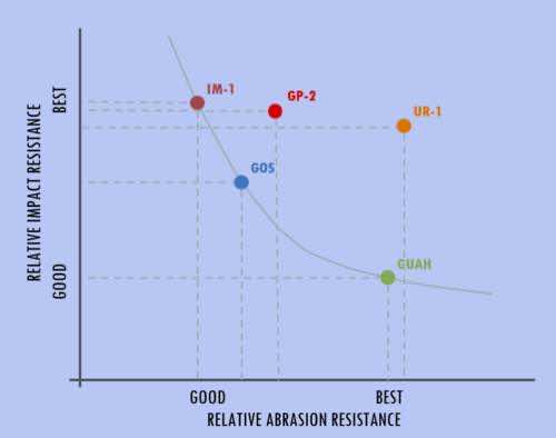
The newest cutter families from SMT are the:
GP-2 and UR-1.
The GP-2 provides impact resistance equivalent to E6’s leading impact cutter (IM-1) with greatly improved abrasion/thermal resistance.
The UR-1 provides abrasion resistance better than E6’s leading abrasion cutter (GUAH) with a significant increase in spall resistance using a multimodal diamond grain size distribution and ultra high pressure sintering.
SMT also continues to offer the GOS cutter family for the mid-tier performance band.
Destructive testing
Abrasion (wear) resistance
Turning of a stone bar, typically granite.
Parameters - depth of cut approximately 0.5 mm, feed rate approximately 0.1 mm/rev and test time about 3 minutes; both dry and with coolant. PDC flank wear depth is measured.
Wear v Average diamond grain size (mono-modal)
An additional heavy wear test is sometimes used; the spiral cutting of granite (diameter approximately 1m) on a vertical turret lathe.
Parameters - depth of cut approximately 0.25 mm, feed rate approximately 5 mm/rev and a rake angle of approximately 20°.
Impact resistance (drop test)
Parameters - initial impact energy approximately 20 J, repeated impacts are carried out to see if any spalling occurs. If there is no spalling then the impact energy is increased and the test sequence repeated. The result are typically reported as impact energy, number of impacts and spall area.
It should be noted that the hardness of the impact anvil is crucial and it should be controlled.
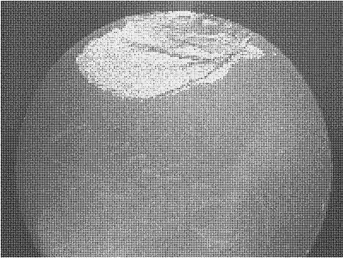
Spall area of 15%
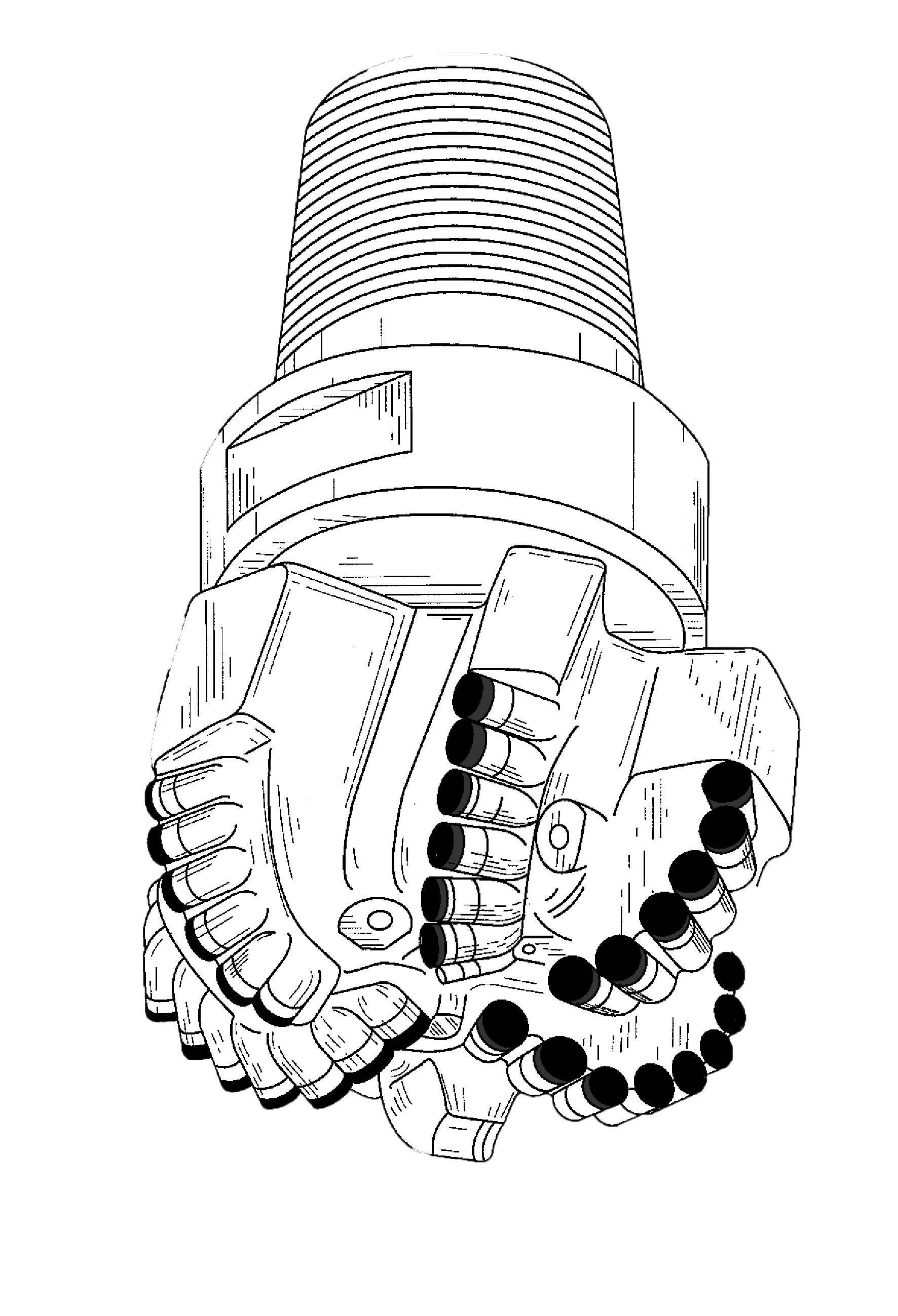
As previously mentioned, laboratory tests are used to indicate PDC performance. But, when PDC is used on a bit, wear can be extreme, as shown in the schematic of a worn bit blade. Cutters suffer severe wear in critical parts of the bit, in addition, diamond layers can suffer complete spalling / delamination.


Schematic of worn PDC bit blade
PDC bits have many cutting elements, as the bit drills, the cutter paths overlap one another resulting in different loading / wear areas on each PDC.
Effect of Heat
Because most PDC are brazed to a bit body or extension stud, it is important to understand the behaviour of PDC under the influences of temperature, time, atmosphere, flux and molten braze alloy.
Thermal stability
This test typically involves 5 min in argon, at 770 ℃, in a tube furnace.
Abrasion (wear) resistance, mentioned above, is used to detect any thermal degradation of the diamond layer. The graph shows the results from a batch of test PDC.
Braze bath test
Test duration approximately 30 mins at 680/700 ℃.
After cooling, die penetrant is used to detect any cracks.
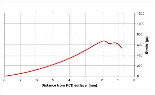
Back grinding
By fitting a strain gauge to the PCD layer and removing the substrate, in stages, by grinding, the substrate strain profile can be determined.
This data can be used to verify finite element (FE) models.
Non-destructive testing
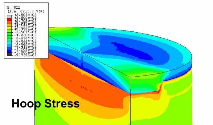
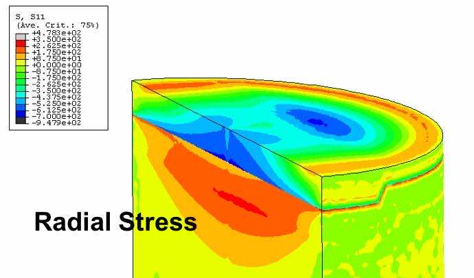
The total stress state of a PCD cutter is a combination of:
- residual stress caused by mismatch in thermal and elastic properties and
- operation stress caused by forces acting on the bit.
Residual stresses can be optimised by using FE analysis using a linear elastic model with thermal and elastic properties. An applied load analysis can be used to model spalling, chipping and heat generated cracking.

Laboratory testing determines properties such as:
Longitudinal speed of sound
Transverse speed of sound
Density
Young’s modulus
Bulk modulus
Shear modulus
Poisson’s ratio
Microstructure
Interface
Substrate
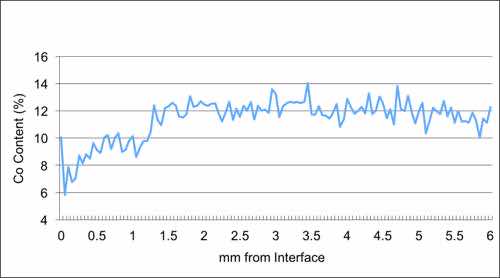
Cobalt content
Denuded zone
Width of denuded zone
| Property | Value |
|---|---|
| Vickers Hardness (GPa) | 70-90 |
| Fracture Toughness (Mpam0.5) | 7-13 |
| Transverse Rupture Strength (Mpa) | 1,200-1,600 |
| Young's Modulus (GPa) | 750-1,000 |
| Compressive Strength (GPa) | 6.9-7.6 |
| Coefficient of Friction | 0.05-0.1 |
| Coefficient of Thermal Expansion (10-6℃) | 3.6-4.6 |
| Thermal Conductivity (W/m/°K) @20℃ | 300-560 |
| Speed of sound (longitudinal) (km/s) | 13-17 |
| Speed of sound (transverse) (km/s) | 10-11 |
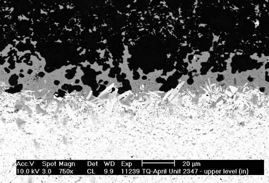
Interface
In the Scanning Electron Micrograph above, polycrystalline diamond is at the top and the cemented carbide substrate at the bottom.
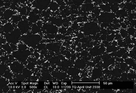
Polycrystalline diamond layer
In the Scanning Electron Micrograph above, diamond is black and the metallic binder is white.
Standard cutter specifications
∅ (mm)
13.44
15.88
19.05
H (mm)
8.00
13.20
16.00
L (mm)
0.25
0.30
0.40
0.45
0.50